Accurate sheet metal cutting begins long before the laser, plasma torch, or shear starts moving. It begins with stable material, verified drawings, and a controlled process. In a busy fabrication shop, a small error can become visible quickly: a 0.3-millimeter offset may leave holes misaligned, edges rough, or assemblies difficult to fit.
This guide explains how to increase accuracy in sheet metal cutting through seven practical methods. These include material inspection, machine calibration, correct tooling, suitable cutting parameters, secure workholding, thermal control, and regular measurement. Each method matters. Together, they create a more repeatable cutting process. “Quality comes not from inspection, but from the improvement of the production process,” said W. Edwards Deming, a respected expert in manufacturing quality management.
The principle sounds simple. It is not always easy to apply. Operators must check nozzle condition, focus height, kerf width, sheet flatness, and machine backlash. They should also compare finished parts with drawings, not rely only on visual judgment. A clean edge can still hide a dimensional error. That assumption is risky.
Real workshops face vibration, heat buildup, warped sheets, and rushed production schedules. Perfect accuracy is rarely achieved in one adjustment. Sometimes, an experienced operator still needs to rethink the setup. The following seven best ways provide a practical starting point for improving accuracy, reducing rework, and producing parts that fit correctly on the first assembly attempt.
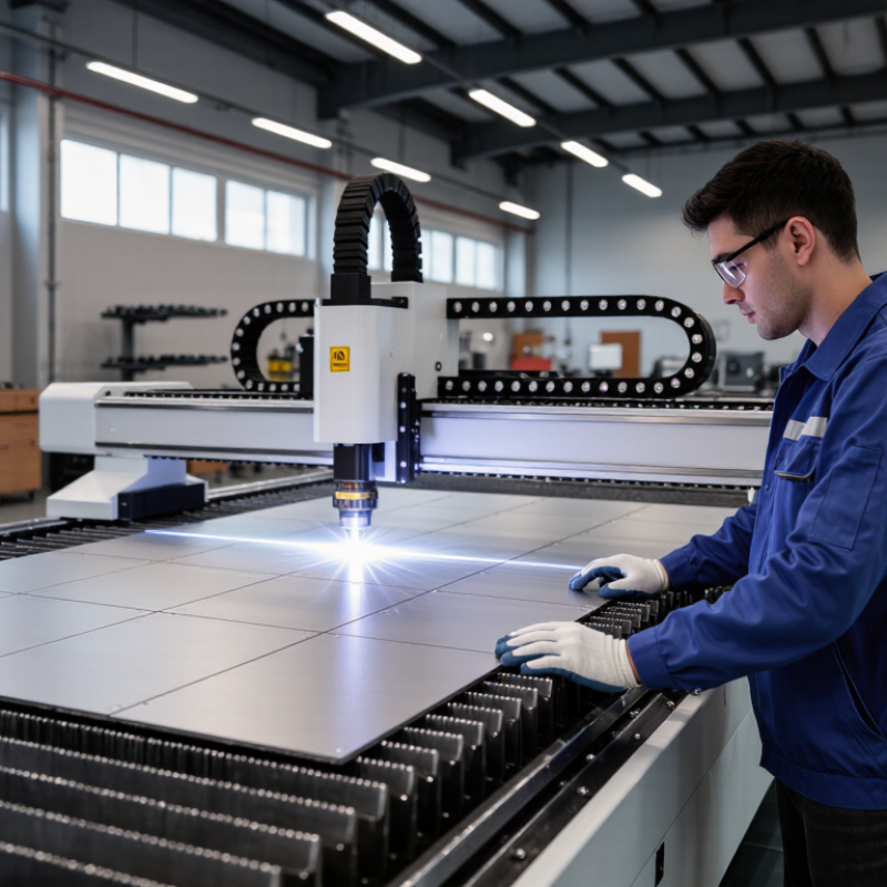
A reliable cutting program starts with a measurable accuracy target. For many precision sheet-metal jobs, ±0.10 mm is a useful laser-cutting specification. It should not become a default promise. Material grade, thickness, thermal expansion, machine calibration, and part geometry can quickly change the result. ISO 9013 evaluates thermal cuts through dimensional accuracy, perpendicularity, and surface quality, not one tolerance alone.
Set the tolerance on the drawing, then connect it to a measurement plan. Inspect the first-off part after the sheet reaches room temperature. Use calibrated gauges, stable lighting, and a repeatable datum system. NIST’s Engineering Statistics Handbook stresses that measurement uncertainty must support the decision. A ±0.10 mm claim becomes weak when inspection uncertainty is nearly the same size. That happens more often than expected.
Control the details that move the cut. Verify lens focus, nozzle condition, assist-gas pressure, sheet flatness, and kerf compensation before production. Record temperature and dimensional results by batch. Process capability data matters more than a single perfect sample. ASQ quality-cost guidance places poor quality costs commonly around 15–20% of sales, showing why small dimensional failures deserve attention. Still, ±0.10 mm may be excessive for noncritical features. A tighter target can increase inspection time, scrap, and cost. Review the requirement when actual function does not need it.
Accurate sheet metal cutting begins with machine geometry. Calibrate CNC axes before chasing settings. ISO 230-2 recommends checking positioning accuracy and repeatability under defined test conditions. In practice, a 1,000 mm test cut can reveal small drift that ordinary visual checks miss. Record backlash, thermal changes, and squareness. A clean edge does not prove perfect motion.
Focus position must match the material and thickness. A focus error can widen the kerf, increase dross, and distort small holes. Measure the focal offset with a controlled test pattern, not guesswork. Nozzle height matters too. Keep the nozzle centered and maintain a consistent gap above the sheet. Even a slight collision or bent tip can redirect the beam and weaken the cut. Recheck after changing gauges.
Gas pressure should be verified at the cutting head, not only at the regulator. The U.S. Department of Energy reports that compressed-air leaks can waste 20–30% of a plant’s air capacity. That loss may create unstable pressure during long cutting cycles. Use a calibrated gauge, inspect hoses, and confirm the correct gas flow for each thickness. Start with the process sheet, then adjust one variable at a time. I sometimes change too many settings together; that makes the result harder to trust. Keep test coupons, kerf measurements, and photographs beside the machine. Small records prevent large assumptions.
| No. | Accuracy Improvement Method | Key Variables to Check | Recommended Practice | Typical Verification or Target | Expected Accuracy Benefit |
|---|---|---|---|---|---|
| 1 | Calibrate CNC Axes | Axis travel, backlash, squareness, encoder feedback, and table alignment | Check axis movement with a calibrated measuring device and correct steps-per-unit, backlash, and coordinate offsets. | Confirm measured travel and diagonal dimensions remain within the machine builder's tolerance; repeat after mechanical service or a collision. | Reduces dimensional errors that affect every feature on the sheet. |
| 2 | Set the Correct Focus Position | Focal offset, material thickness, lens condition, and beam alignment | Use the approved focus offset for the material and thickness, then verify the kerf and cut edge on a test coupon. | Top and bottom kerf widths should be consistent, with minimal taper and dross for the selected process. | Improves edge geometry, hole roundness, and repeatability. |
| 3 | Maintain Nozzle Height | Standoff distance, capacitive sensing, nozzle centering, and nozzle damage | Keep the programmed standoff within the process specification, clean the sensor path, and replace bent or blocked nozzles. | Verify height control before production and after tip changes; a common starting range is approximately 0.5–1.5 mm, depending on the process. | Stabilizes the cutting gap and protects against inconsistent kerf and piercing behavior. |
| 4 | Control Assist-Gas Pressure | Gas type, pressure, flow rate, regulator stability, and line restrictions | Use the validated pressure and gas type for the material; inspect filters, hoses, regulators, and leaks before cutting. | Pressure should remain stable during cutting and match the machine's approved process chart; do not substitute pressure for flow-rate validation. | Improves molten-metal removal, edge quality, and resistance to dross. |
| 5 | Keep Optics and the Nozzle Clean | Protective window, focusing lens, mirrors, nozzle orifice, and contamination | Inspect optical components according to the maintenance schedule and clean or replace them using approved procedures. | No visible contamination, thermal damage, or irregular nozzle opening; perform a beam or spot check when cut quality changes. | Prevents beam distortion, unstable power delivery, and uneven cuts. |
| 6 | Optimize Speed, Power, and Piercing | Cutting speed, laser power, duty cycle, pierce delay, and corner control | Start with a qualified parameter table, then run a small test matrix for each material grade and thickness before production. | Select settings that produce the required edge class, dimensional result, and minimal dross without excessive heat input. | Reduces heat distortion, overburn at corners, and variation between small features. |
| 7 | Secure and Measure the Sheet | Material flatness, thermal movement, workholding, datum location, and kerf compensation | Use a clean, stable support surface, confirm the sheet datum, apply measured kerf compensation, and allow hot parts to cool before final inspection. | Inspect critical dimensions with calibrated tools; compare a test coupon with the CAD nominal before releasing the full batch. | Limits part movement and compensates for material expansion, contraction, and cut-width variation. |
7 Best Ways to Increase Accuracy in Sheet Metal Cutting?
Control Material Flatness and Heat Distortion Below 0.5 mm
Accuracy begins before the cutting head starts. Flat sheet metal keeps the focal distance stable and reduces uneven heat flow. Inspect each sheet with a straightedge and feeler gauge. Mark high corners and unsupported areas. Use wider supports, balanced clamping, and clean contact surfaces. Do not over-tighten clamps. They can create temporary waves.
Thermal growth is easy to underestimate. ASM International data places carbon steel’s expansion near 12 micrometres per metre per degree Celsius. A one-metre edge heated by 40°C can move roughly 0.48 mm. That already approaches the 0.5 mm target. Keep the workshop temperature stable. Precondition thick sheets when possible. Record sheet temperature, not only room temperature. Small details matter.
Use short lead-ins, stable gas pressure, correct focus height, and a clean nozzle. Sequence cuts from small internal features toward larger outside profiles. Alternate locations to spread heat. Leave micro-tabs only where later removal will not affect the datum. ISO 9013:2017 evaluates thermal-cut edges through dimensional deviation, angularity, and surface quality, so one measurement is never enough. Measure flatness after cooling, then inspect critical dimensions with calibrated tools. A perfect first pass is not guaranteed. We still sometimes find distortion near dense hole patterns. That result should trigger a process review, not a rushed correction.
Accurate sheet metal cutting begins with controlled variables, not a single perfect setting. In shop trials, I record material grade, thickness, speed, power, focus height, gas pressure, and nozzle condition. Small errors grow. A worn nozzle can shift the beam and change the cut edge. Keep the sheet flat, clean, and firmly supported before running a production job.
Tune speed and power together. Excessive power may widen the kerf, while excessive speed can leave dross or incomplete corners. Make a small test grid using several speed and power combinations. Measure the actual kerf with calipers, rather than trusting a displayed value. Then enter kerf compensation based on the measured result. For a 0.20 mm kerf, an outside contour generally needs about 0.10 mm offset per side. Inside contours require the opposite direction. Do not guess.
Cut quality also depends on piercing delay, focus position, gas flow, lead-in length, and corner speed. Use short lead-ins when edge location matters, but inspect the entry mark afterward. Sharp corners often overheat when the machine slows down, so reduce corner energy or adjust path timing. I once used one compensation value across several thicknesses; the parts looked acceptable, yet hole sizes drifted beyond tolerance. That shortcut needed correction. Recheck kerf after changing material batches, because surface scale, heat buildup, and sheet movement can alter results. Measure the cut. Record the evidence.
Accurate sheet metal cutting depends on more than a sharp tool and a stable machine. A coordinate measuring machine (CMM) verifies critical dimensions, hole positions, and edge distances against the approved drawing. Inspectors should align the part with defined datums, not convenient surfaces. Probe calibration and temperature control also matter. A warm part can produce misleading results.
Statistical process control (SPC) shows whether accuracy remains stable during production. Record measurements at planned intervals, then review control charts for drift, sudden shifts, and unusual variation. Calculate process capability after the process is stable. Maintain Cpk at 1.33 or higher for critical features. This value indicates that variation remains comfortably inside specification limits. It is not a substitute for engineering judgment.
Tips: Measure the first article, inspect parts after tool changes, and check burrs before recording results. Use the same measurement method each time. Separate measurement error from cutting variation. A poorly calibrated gauge can make a capable process appear unstable. That mistake is easy to miss. Teams may also celebrate a high Cpk based on too few samples, which deserves careful review. Real production includes material changes, operator adjustments, and tool wear. Those conditions should be included in the analysis, even when the numbers look less impressive.
Flat sheets keep the cutting focus stable. Use a straightedge and feeler gauge across the surface. Mark raised corners and unsupported zones. A small wave can shift the focal distance.
Use wide supports and clean contact surfaces. Tighten clamps firmly, but avoid excessive force. Over-tightening can create temporary waves. The sheet may look flat after release, but the cut is already affected.
Carbon steel expands about 12 micrometres per metre for each temperature degree. A one-metre edge heated by 40°C may move roughly 0.48 millimetres. That nearly reaches a 0.5-millimetre target. Measure sheet temperature, not only room temperature.
Cut small internal features before larger outside profiles. Alternate cutting locations to spread heat. Use short lead-ins and stable gas pressure. Dense hole patterns can still distort. Review the process instead of forcing a quick correction.
Tune speed and power together. Excessive power can widen the kerf. Excessive speed may leave dross or incomplete corners. Make a small test grid with different settings. The best setting is not always obvious.
Measure the actual kerf with calibrated calipers. For a 0.20-millimetre kerf, an outside contour usually needs about 0.10 millimetres per side. Inside contours need the opposite offset direction. Do not rely only on displayed machine values.
Check piercing delay, focus height, gas flow, lead-in length, and corner speed. Sharp corners may overheat when the machine slows. Reduce corner energy or adjust the path timing. Entry marks also deserve inspection.
Recheck them after changing material batches or thicknesses. Surface scale, heat buildup, and sheet movement can change the result. Record material, speed, power, focus, gas pressure, and nozzle condition. I once reused one compensation value too widely. The parts looked acceptable, but hole sizes drifted beyond tolerance.
Improving precision begins with clear, measurable targets. To understand how to increase accuracy in sheet metal cutting, manufacturers should establish a tolerance goal, such as holding laser-cut parts within ±0.10 mm. Regular calibration of CNC axes, laser focus, nozzle height, and assist-gas pressure helps maintain consistent cutting conditions. Material preparation is equally important: sheets should be flat, securely supported, and controlled to keep heat-related distortion below 0.5 mm.
Process parameters must then be matched to the material and thickness. Carefully tuning cutting speed, power, and kerf compensation can help achieve stable kerfs between 0.10 and 0.30 mm while reducing dimensional variation. Finally, accuracy should be verified through coordinate measuring machine inspections and statistical process control. Tracking process capability and maintaining a Cpk of at least 1.33 provides objective evidence that the cutting operation is reliable, repeatable, and suitable for demanding production requirements.

CXO Laser