Laser cutting quality rarely depends on one machine setting. It emerges from the relationship between material, thickness, lens, nozzle, gas, power, speed, and focus. A stainless-steel sheet may need a different approach after its surface becomes warm, scratched, or slightly oxidized. Small changes can create wide kerfs, rough edges, dross, or incomplete cuts.
This guide explains how to optimize laser cutting parameters through practical, repeatable adjustments. It focuses on seven proven methods used by experienced operators and process engineers. These methods include selecting suitable power and speed, setting accurate focus, controlling assist gas, choosing the right nozzle, and managing heat accumulation. Each recommendation should be tested against the machine manufacturer’s specifications and the material supplier’s guidance. Safety interlocks, ventilation, protective equipment, and documented operating procedures remain essential.
Measure before changing everything. A controlled test grid can reveal whether speed or power causes the defect. Examine the cut face under good lighting, check the kerf width, and record the results beside each sample. Production experience shows that the fastest cut is not always the most economical one. A clean edge may require slower movement, higher gas pressure, or better focus. Some materials behave unpredictably, and even experienced technicians can misread a defect. That uncertainty matters. The goal is not a perfect setting on paper, but a stable process that produces consistent parts, reduces waste, protects equipment, and remains reliable across normal production variations.
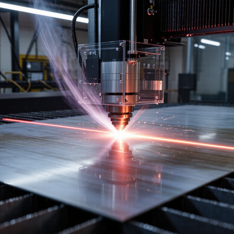
Identify the material before changing machine settings. Carbon steel, stainless steel, aluminum, and acrylic absorb heat differently. Material grade also matters, especially when coatings or surface oxidation are present. Record the sheet type, thickness, and surface condition before each trial. Small differences can change the cutting response.
Thickness determines the required power, speed, focus position, and assist-gas pressure. Thin sheets may need faster movement to prevent excessive melting. Thick plates often require slower cutting and careful piercing control. Define the cutting requirement clearly: clean edges, tight dimensions, low dross, or maximum production speed. These goals can conflict. A fast cut is not always a precise cut. Inspect the edge under good lighting, and check the kerf width with calipers. A clean appearance can still hide dimensional errors.
Tips: Use a small test coupon first. Change one parameter at a time. Watch for dross on the lower edge, a wide kerf, discoloration, or incomplete penetration. Keep notes with exact values and observations. The first setting is rarely perfect. Even experienced operators can overlook material variation. Review failed cuts honestly, because the problem may involve focus, nozzle alignment, or an incorrect material assumption rather than power alone.
Laser cutting quality rarely comes from power alone. Power, cutting speed, and pulse frequency must be tuned as a group. Begin with a small test grid on the same material and thickness as the final job. Change one setting at a time, then inspect the kerf, edge color, dross, and cut-through consistency. Record every result.
Set laser power high enough to penetrate the sheet, but avoid excessive heat. Higher power can widen the kerf and leave a rough lower edge. Increase cutting speed gradually when the edge looks burned or heavily melted. Reduce speed when the beam fails to pass through, especially around corners. Pulse frequency matters on pulsed systems. A higher frequency creates more overlapping pulses and can smooth the cut, but it may also build heat. Lower frequency can reduce heat input, though the edge may become uneven.
Keep the focus position, assist-gas pressure, nozzle height, and material cleanliness consistent during testing. Otherwise, the results become difficult to trust. I once blamed low power for incomplete cuts, but a dirty nozzle caused the real problem. That mistake was expensive in time. Use a microscope or strong side lighting when possible. Small striations often reveal unstable speed or focus. Maintain a parameter log with material lot, thickness, and ambient conditions. The best setting is not always the fastest one; it is the setting that delivers repeatable edges with acceptable energy use and minimal rework.
7 Best Ways to Optimize Laser Cutting Parameters
Adjust Focus Position, Nozzle Height, and Beam Alignment
A stable cut begins with the focal position. Set the focus near the material’s upper surface for thin sheets, then test a slightly deeper position on thicker plate. A 0.5 mm shift can change kerf width, edge taper, and dross noticeably. I measure the cut edge, rather than trusting the machine display. Material flatness often makes the “correct” focus less correct across one sheet.
Nozzle height deserves equal attention. Keep the standoff consistent, commonly around 0.5–1.0 mm, according to process guidance used in industrial laser cutting. Too much distance weakens the assist-gas flow. Too little distance increases collision risk and contamination. The U.S. Department of Energy estimates that compressed-air leaks can waste 20–30% of compressor output, so unstable gas delivery should not be mistaken for a bad focus setting. Small leaks matter.
Beam alignment must keep the beam centered through the nozzle orifice. Check the burn mark at several positions on the worktable. An off-center mark usually creates uneven kerf lines and dross on only one side. ISO 9013:2017 evaluates thermal-cut edges through features such as perpendicularity, roughness, and dross. Power, speed, gas pressure, and pierce time should be tuned after these three mechanical checks. My own trials still fail occasionally; a clean edge at one corner can hide poor alignment elsewhere.
Practical starting points for improving cut quality, speed, and process stability
| No. | Optimization Method | Typical Starting Point | Target or Control Indicator | Expected Benefit | Adjustment Guidance |
|---|---|---|---|---|---|
| 1 | Set the focus position | For flat sheet cutting, begin at the top surface or approximately 0.5–1.5 mm below the surface, depending on material thickness and kerf requirements. | The narrowest kerf, consistent cut-through, and minimal dross on the lower edge. | Improves energy distribution through the material and stabilizes the cut front. | If the top edge is wide but the bottom does not separate, move the focus slightly downward. If the upper edge becomes excessively melted, move it upward. |
| 2 | Set the nozzle height | Use approximately 0.7–1.0 mm for oxygen cutting and 0.8–1.5 mm for nitrogen or air cutting, subject to the cutting head and nozzle design. | Stable gas flow, no nozzle collision, and a centered, symmetrical kerf. | Maintains gas concentration and pressure at the cut, reducing dross and process fluctuations. | A height that is too large can weaken gas flow; a height that is too small increases collision risk and sensitivity to warped sheet. |
| 3 | Check beam and nozzle alignment | Verify the beam passes through the nozzle center using a low-power pulse test and suitable alignment paper or tape. | The pulse mark should be centered within the nozzle opening, with a practical offset of no more than about 0.1–0.2 mm. | Prevents uneven gas flow, tapered cuts, edge discoloration, and inconsistent kerf width. | If cut quality changes when the cutting direction changes, inspect beam centering, protective optics, nozzle condition, and head squareness. |
| 4 | Match cutting speed to power density | Change speed in small steps of approximately 5–10% while keeping material, thickness, focus, gas, and nozzle constant. | Complete separation, straight striations, minimal dross, and no excessive heat-affected zone. | Balances productivity with cut quality and reduces unnecessary heat input. | Increase speed when the cut is clean and heat input is excessive. Reduce speed when the beam fails to cut through or leaves heavy bottom dross. |
| 5 | Select the correct assist gas and pressure | Use oxygen for efficient mild-steel cutting; use nitrogen or clean, dry air when a bright, low-oxidation edge is required. Typical pressure ranges are about 0.6–1.2 bar for oxygen and 10–20 bar for nitrogen, depending on thickness and nozzle geometry. | Stable pressure at the cutting head, consistent edge appearance, and controlled dross formation. | Removes molten material, controls oxidation, and supports higher cutting stability. | Increase pressure gradually if molten material remains in the kerf. Excessive pressure can widen the kerf and disturb the cut front. |
| 6 | Optimize piercing parameters | Use a separate pierce routine with reduced power or defocused energy, a controlled pierce height, and a short dwell time appropriate to material thickness. | Reliable pierce-through without excessive spatter, lens contamination, or enlarged entry holes. | Reduces failed pierces, protects optics, and improves the first-cut quality. | For thick plate, use staged piercing or a longer pierce cycle. If spatter reaches the nozzle or lens, increase stand-off or reduce piercing energy. |
| 7 | Maintain optics, nozzle condition, and machine calibration | Inspect the protective window and nozzle at each shift or after a collision; replace damaged or visibly contaminated parts and verify axis calibration regularly. | Clean optics, a round and undamaged nozzle orifice, stable power delivery, and accurate motion. | Prevents gradual quality loss, unexpected alarms, dimensional errors, and unstable beam transmission. | If the same program produces changing results, check optics contamination, nozzle wear, cooling, gas supply, bed condition, and motion accuracy before changing cutting parameters. |
Assist gas affects cut speed, edge quality, dross, and operating cost. Oxygen usually supports fast cutting of carbon steel because it adds an exothermic reaction. Nitrogen protects stainless steel and aluminum from oxidation, leaving a cleaner, brighter edge. Argon can suit sensitive applications, but its cost deserves careful review. ISO 9013:2017 provides a useful framework for evaluating thermal-cut quality, including edge roughness and perpendicularity.
Pressure must match material thickness, nozzle size, focal position, and cutting speed. More pressure is not automatically better. Excessive nitrogen can disturb the molten pool, widen the kerf, and increase gas use. Low pressure may leave hanging dross, especially near corners. In production trials, small changes can matter: adjust pressure in 0.1–0.3 bar steps, then inspect the underside and edge under consistent lighting. The perfect setting is rarely universal. That is the difficult part.
Tips: Start with the supplier’s process window, then test three nearby pressure values. Record gas type, pressure, speed, power, nozzle condition, and material heat number. Use a calibrated regulator and check leaks before testing. The U.S. Department of Energy reports that compressed-air leaks commonly waste 20–30% of compressor output, reminding operators that stable delivery matters. ISO 8573-1 also emphasizes controlled compressed-air purity. Moisture or oil contamination can create unstable piercing and inconsistent edges. Do not judge a setting from one sample. Cut a small batch, compare dross and roughness, and revise the parameter sheet when results disagree.
Consistent laser cutting begins with controlled testing, not intuition. Record material grade, thickness, nozzle condition, lens status, and ambient temperature. Then change one variable at a time: power, cutting speed, focus position, gas pressure, nozzle height, pulse frequency, and pierce settings. A small parameter sheet prevents memory-based adjustments. It also exposes repeatability problems.
Inspect every test coupon under the same light. Measure kerf width, edge taper, dross height, heat-affected width, and piercing time. Keep digital images beside numerical results. NIST’s Engineering Statistics Handbook recommends separating repeatability from reproducibility. This distinction matters. One operator may achieve stable results, while another cannot. Use control charts for key dimensions, rather than trusting one attractive sample.
Energy use deserves attention too. The International Energy Agency reported that industry consumed about 37% of global final energy in 2022. Efficient settings can reduce waste without sacrificing edge quality. Start with a conservative speed and moderate power. Refine in small steps. Watch for excessive heat lines, rough lower edges, or delayed piercing. A clean top surface can still hide poor underside quality. That mistake is common. Gas pressure may need adjustment after changing nozzle size, even when the material remains identical. My trial records are rarely perfect; missing a temperature reading can weaken an otherwise useful comparison. Repeat questionable tests before approving production settings. Consistency beats a single fast cut.
Different materials absorb heat differently. Record the material grade, thickness, coating, and surface condition. Small variations can change cutting behavior.
Thickness influences power, speed, focus position, and assist-gas pressure. Thin sheets usually need faster movement. Thick plates often need slower cutting and controlled piercing.
Decide whether you need clean edges, accurate dimensions, low dross, or higher production speed. These goals may conflict. Fast cutting is not always precise.
Cut a small coupon before processing the full sheet. Change one parameter at a time. Watch for dross, wide kerfs, discoloration, and incomplete penetration.
Use strong lighting to inspect the edge. Measure kerf width with calipers. A smooth-looking edge can still contain dimensional errors.
For thin sheets, place the focus near the upper surface. For thicker plates, test a slightly deeper focus. A 0.5-millimeter shift can change dross and edge taper.
A consistent standoff is essential. Industrial guidance commonly uses about 0.5–1.0 millimeters. Excessive distance weakens gas flow. Too little height raises collision risk.
Check the burn mark through the nozzle at several table positions. An off-center mark may cause uneven kerfs and dross on one side.
Record exact settings and visible results. Review focus, nozzle alignment, gas delivery, and material assumptions. My first setting is rarely perfect.
Yes. Small compressed-air leaks can reduce gas stability. Check the delivery system before changing focus or power again. I sometimes overlook this.
Optimizing laser cutting parameters begins with understanding the material, its thickness, and the desired cutting requirements, including edge quality, accuracy, and production speed. The key settings include laser power, cutting speed, and pulse frequency, which must be balanced to achieve effective energy transfer without excessive melting, burning, or incomplete cuts. Focus position, nozzle height, and beam alignment should also be adjusted carefully to maintain a stable and concentrated beam throughout the process.
To learn how to optimize laser cutting parameters, select an appropriate assist gas and fine-tune its pressure according to the material and cutting conditions. Gas flow can influence heat removal, debris clearance, and edge cleanliness. Finally, conduct controlled test cuts, measure the results, and refine one setting at a time. Recording successful combinations helps improve consistency, reduce waste, and create a reliable parameter guide for future projects.

CXO Laser