Laser cutting ceramics appears precise, clean, and highly controllable. The reality is less forgiving. Ceramic materials combine high hardness, low ductility, and poor tolerance to sudden temperature changes. These properties make them difficult to process without edge chipping, thermal cracks, or hidden subsurface damage.
So, what are common problems in laser cutting ceramics? Typical failures include heat-affected zones, recast layers, taper, microcracks, and inconsistent kerf width. Fraunhofer Institute for Laser Technology publications on ceramic micromachining repeatedly identify thermal stress and crack formation as key process risks. The European Commission’s Best Available Techniques Reference Document for the Ceramics Manufacturing Industry also highlights energy-intensive firing and strict quality control requirements. These factors explain why laser parameters cannot be copied directly between alumina, zirconia, silicon nitride, and glass-ceramics.
Small details matter. A darkened edge may indicate excessive heat. White powder near the cut can signal brittle fracture or incomplete material removal. Assist-gas pressure, pulse duration, beam focus, scanning speed, and material porosity can change the result within seconds. ISO 11553-1 also emphasizes controlled laser-processing safety and equipment evaluation, reinforcing the need for documented procedures and trained operators.
No process is perfect. Even experienced teams sometimes optimize surface appearance while missing internal cracks. A reliable evaluation should combine microscopy, dimensional checks, and strength testing. This article examines the causes behind common ceramic-cutting defects and explains practical ways to reduce them through measurable process control.
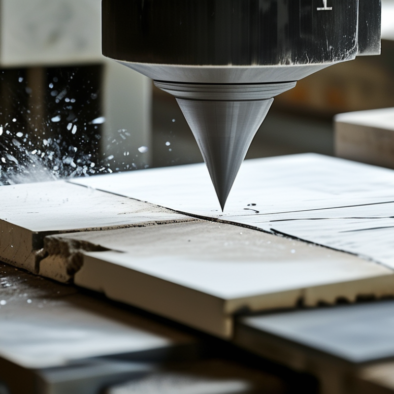
Ceramics behave differently from metals during laser cutting. Their hardness resists mechanical damage, but their brittleness makes thermal stress dangerous. A narrow heat zone can still create microcracks along the cut edge. Some ceramic grades also conduct heat poorly. Heat then remains near the beam path and forms a rough, chipped kerf. This effect becomes stronger in dense sections. It can happen quickly.
Thermal expansion is another important factor. Even slight expansion differences may separate grains or open hidden pores. Alumina, zirconia, and glass-ceramic materials also absorb laser energy differently. Surface color, glaze, porosity, and thickness change the cutting response. A setting that works on a polished sample may fail on a textured one. Laser wavelength matters too. Reflective surfaces may need different energy delivery than matte surfaces. Short pulses often limit heat buildup, but they can reduce cutting speed. Higher power is not always better.
Practical trials should use small test coupons from the same ceramic batch. Check the edge under magnification, not only by touch. Look for white chips, darkened zones, and hairline cracks. Focus position, pulse overlap, cutting speed, and assist gas require careful adjustment. I have found that “clean” edges can still hide damage. That assumption needs testing. Moisture and internal stress may also change results between batches. Reliable process control means recording these variables and inspecting several samples before production.
Why Are There Common Problems in Laser Cutting Ceramics?
Common Defects Caused by Heat and Thermal Stress
Laser cutting ceramics is difficult because heat enters a brittle, non-metallic structure. The beam can create a narrow molten zone, while nearby material remains comparatively cold. This uneven expansion produces tensile stress and microcracks. ASM Handbook, Volume 4A, places alumina’s thermal expansion near 7–8 × 10⁻⁶ K⁻¹, depending on purity and temperature. Zirconia usually expands more, while silicon nitride expands less. Material choice matters.
The visible defects are familiar: edge chipping, dark heat-affected zones, taper, and delayed fracture. A 2022 review in the Journal of the European Ceramic Society links these failures to thermal gradients, residual stress, and unstable crack growth. Cutting too quickly may leave incomplete separation. Cutting too slowly can overheat the edge. Small cracks spread.
Process records should include pulse energy, repetition rate, scan speed, assist gas, and cooling conditions. The Fraunhofer Institute’s laser-processing research repeatedly emphasizes controlled energy delivery and heat management for brittle materials. In practice, a preheated workpiece can reduce thermal shock, but excessive preheating may enlarge the damaged zone. This is where many settings fail. Operators often optimize speed first, then inspect stress later. That approach needs reconsideration. Polarized-light inspection, microscopy, and three-point bending tests can reveal damage that looks invisible to the naked eye. Ceramic grade, thickness, surface finish, and fixturing must be evaluated together.
Laser cutting ceramics is difficult because the material resists heat flow. A narrow laser spot can create a hot surface while the surrounding area stays relatively cool. This uneven expansion produces internal stress. Cracks may begin near a pierced hole, then spread along the cutting path. Chipping often appears when brittle grains break away during piercing or when the beam exits the workpiece.
Edge damage usually comes from excessive energy, unstable focus, or unsuitable cutting speed. A rough support surface can also transfer vibration into the ceramic. In practical trials, small changes in thickness can require different settings. I inspect the underside as carefully as the top edge. It often reveals hidden fractures. No setting works perfectly every time, and that limitation deserves attention.
Tips: Use test pieces before production. Adjust power and speed gradually. Keep the focus consistent across the surface. Support thin sheets evenly, especially near the cutting line. A slower entry may reduce chips, but excessive heat can worsen cracking. Clean dust from the surface and check the nozzle regularly. Leave sharp corners for later finishing when possible. I also mark the crack direction after each test. This simple record helps separate machine problems from material variation.
Laser cutting ceramics often becomes unreliable when material settings are treated as fixed numbers. Ceramic composition, thickness, surface glaze, and moisture can change the cutting response. A setting that works on a dense tile may crack a porous ceramic sheet. Small differences matter.
Power controls heat input, while speed controls how long that heat remains in one area. Excessive power can create dark edges, microcracks, or chipped corners. Excessive speed may leave an incomplete cut. Frequency also affects pulse overlap and edge stability, especially with brittle materials. Focus should sit precisely on the surface or slightly within the material. A small focus error can widen the kerf and reduce dimensional accuracy.
In practice, I use a test grid before cutting valuable parts. I vary power, speed, frequency, and the number of passes across small samples. Air assistance can remove debris, but too much pressure may disturb fragile edges. I inspect the underside with magnification because hidden cracks often appear there first. The result is not always predictable. I have sometimes trusted a previous recipe too much and ignored a changed batch of ceramic. That mistake produced clean-looking edges with internal fractures. Slower passes may improve separation, but they can also increase thermal stress. Material settings need measurement, observation, and occasional revision.
Why Are There Common Problems in Laser Cutting Ceramics?
Laser-cut ceramics often develop edge chipping, microcracks, discoloration, and rough kerfs. Alumina is especially sensitive because its thermal conductivity is commonly listed at 20–30 W/m·K, while its fracture toughness is often only 3–5 MPa·m½, according to ASM Handbook, Volume 18. Heat can therefore build quickly, then release through brittle fracture. The visible edge may look acceptable. Hidden damage may remain.
Reducing defects starts with controlled energy. Use shorter pulses and lower heat input when possible. Test several scanning speeds, rather than trusting one setting. A slower speed can deepen the cut, but it may enlarge the heat-affected zone. Preheating the ceramic can reduce thermal shock. A thin sacrificial layer under the workpiece may also limit back-side breakout. Clean, dry compressed gas helps remove particles from the kerf. However, excessive gas pressure can worsen edge erosion. This detail is easy to miss.
Tips: Inspect both faces under angled light. Measure chipping with a calibrated microscope. Use ASTM C1161-style strength testing after process changes. Do not judge quality by appearance alone. A 2023 review in Ceramics International also emphasizes that defects depend on material purity, porosity, pulse duration, and cooling conditions. The process is not perfectly predictable. Record every trial, including failed ones. Those results often reveal the real process window.
Thermal stress is a major cause of edge chipping, microcracks, and heat-affected zones during laser cutting. The chart compares approximate room-temperature linear thermal expansion coefficients for common technical ceramics. Materials with higher expansion values generally require tighter control of laser power, pulse duration, cutting speed, cooling, and preheating to reduce defects. Values vary by material grade and measurement range.
: Ceramics resist mechanical wear but remain brittle. Uneven heating creates thermal stress near the beam path. Microcracks may form quickly.
Thermal conductivity, expansion, porosity, glaze, color, texture, grade, and thickness all matter. Dense sections may retain heat longer.
No. Excessive power can enlarge the heat-affected zone and worsen edge damage. Short pulses may reduce heat buildup but lower cutting speed.
Typical defects include edge chipping, rough kerfs, darkened zones, taper, hairline cracks, and delayed fracture. Some damage stays hidden.
Ceramic batches may differ in moisture, internal stress, porosity, and surface finish. A polished sample may not represent a textured surface.
Use small test coupons from the same ceramic batch. Adjust focus, pulse overlap, speed, assist gas, and cooling conditions carefully.
Moderate preheating may reduce thermal shock. Excessive preheating can enlarge the damaged area. The correct range requires testing.
Inspect cut edges under magnification. Look for white chips, dark zones, and fine lines. Microscopy and polarized-light inspection can reveal more.
Not always. A smooth edge can still contain internal cracks. Three-point bending tests may expose weakness before production use.
Record pulse energy, repetition rate, scan speed, gas flow, focus position, material thickness, and cooling conditions. Small details matter.
Laser cutting ceramics can produce precise shapes, but the process is affected by the material’s hardness, brittleness, low thermal conductivity, and sensitivity to sudden temperature changes. These properties make it difficult for heat to dissipate evenly, often causing thermal stress, discoloration, rough edges, microcracks, chipping, and dimensional inaccuracies. Understanding what are common problems in laser cutting ceramics helps operators identify the causes of poor results and select more suitable processing conditions.
Cutting accuracy and surface quality depend heavily on material thickness, ceramic composition, laser power, cutting speed, pulse duration, focus position, and assist-gas flow. Excessive heat may enlarge the affected zone and create cracks, while insufficient energy can lead to incomplete cuts or uneven edges. Defects can be reduced by using controlled energy input, optimizing speed and focus, applying multiple lighter passes when appropriate, securing the workpiece properly, and allowing sufficient cooling between operations. Careful testing and gradual parameter adjustment are essential for achieving cleaner cuts and minimizing damage.

CXO Laser