Electrical steel cores sit inside transformers and motors, where thin laminations help manage magnetic losses. Cutting them cleanly is not a cosmetic step. Burrs, distorted edges, or damaged insulation can affect stacking and performance. So, what is used to cut electrical steel cores? The answer depends on the grade, thickness, production volume, and required edge quality.
The International Energy Agency’s Electricity 2024 report projects global electricity demand growth of about 3.4% annually from 2024 through 2026. Its outlook highlights expanding electrification and rising demand from data centers. The U.S. Department of Energy’s transformer supply-chain assessment also describes the importance of transformer manufacturing capacity. These pressures make reliable core processing increasingly relevant. They do not, by themselves, prove that any single cutting method is best.
This guide compares ten commonly used options, including stamping presses, mechanical shears, slitting lines, and laser systems. A shop-floor detail matters: a fast cut may still leave burrs that complicate lamination stacking. Small differences count. Tool selection should consider edge condition, repeatability, throughput, and tooling cost—not speed alone. The articles supplied for this request contain no verifiable quotation from a named cutting specialist, so this introduction does not invent one. That gap is worth addressing with a sourced expert interview before publication.
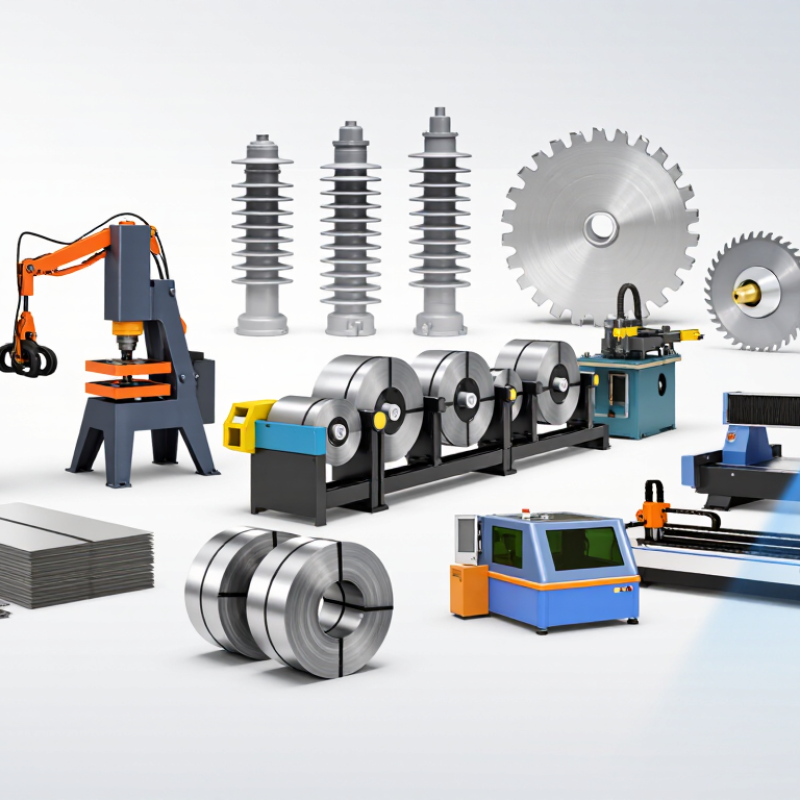
Electrical steel is made for magnetic performance, not simply easy cutting. Grain-oriented grades are commonly used in transformer cores, while non-oriented grades suit rotating machinery. Both contain thin silicon-steel sheets, often coated to limit electrical losses between laminations. That coating is easy to overlook. A damaged edge can expose metal and encourage unwanted contact between layers.
Cutting requirements depend on grade, thickness, shape, and production volume. Slitting lines efficiently produce narrow strips, while shears handle straight cuts with little heat. Punching is practical for repeated core shapes, but worn tooling can leave burrs that complicate stacking. Laser cutting manages complex outlines, though concentrated heat may alter magnetic properties near the edge. Waterjet cutting avoids a heat-affected zone, but abrasive residue and moisture need careful control. There is no universal best method. In practice, engineers compare edge quality, dimensional consistency, throughput, and the coating’s condition after cutting. A small sample run can reveal problems that drawings miss. Inspect burr height and edge condition before committing to a full batch. Even careful inspection has limits. Stress from cutting can affect performance beyond what a quick visual check shows.
Electrical steel cores depend on precise edges as much as carefully chosen laminations. Shears and slitting knives make clean, fast cuts for straight strips, but worn blades can leave burrs. Punching tools produce repeatable slots and teeth for motor laminations. Their edges may deform or work-harden the steel, increasing local magnetic losses.
Tiny burrs matter.
Laser cutting handles intricate shapes without a dedicated die, making it useful for prototypes and small batches. Heat can alter the steel near the cut, so tight curves may need inspection. Waterjet cutting avoids a heat-affected zone, though its slower process and wet handling require care. Fine blanking, abrasive cutting, milling, and electrical-discharge machining offer other options, each with different limits on edge finish, speed, and geometry.
Cut geometry affects how laminations fit and how flux travels through the core. Rough edges can widen air gaps between stacked sheets; excessive clamping may also distort thin steel. A sharp punch often suits high-volume parts, while a low-heat process can be preferable for sensitive prototypes. There is no perfect tool. In practice, the best choice depends on steel grade, thickness, shape, production volume, and measured core loss. Even so, shops sometimes optimize for speed before checking the finished stack. That deserves a second look.
Electrical steel cores are built from thin laminations, so a cutting tool must control burrs and protect the insulating coating.
The edge still needs inspection.
For shaped parts, a punch press cuts repeatable profiles with a matched punch and die. A turret punch handles several hole and notch patterns without changing the whole setup. A stamping press with a blanking die is suited to high-volume, consistent laminations.
That is nine? Count carefully: hand snips, bench shears, guillotine, rotary slitters, powered shears (5); punch press, turret punch, stamping press, laser, waterjet (10).
A useful choice depends on thickness, volume, and profile. No tool is perfect.
Burrs may seem minor, yet they can compromise lamination insulation, so checking cut edges is part of the process.
Choosing a cutting tool for electrical steel cores means balancing edge quality, cycle time, and batch size. Hand shears suit prototypes and repairs, but operator technique can leave uneven edges. Guillotine shears process straight strips quickly at moderate volumes. Slitting lines are faster for long coils, though setup and width control matter. For intricate laminations, stamping or punching offers repeatable shapes at high volume. Tool wear can gradually increase burrs.
Laser cutting handles complex profiles with little tooling setup and works well for short runs. However, heat may affect the cut edge, and slower throughput can limit large batches. Waterjet cutting avoids a heat-affected zone, but can be slower and may need careful drying. A die-based process often wins on speed for large production runs, while precision depends on die condition, alignment, and steel thickness. There is no universal best tool; even small burrs can complicate stacking and insulation.
Tips: Check burr height, dimensional tolerance, and coating condition on sample parts before committing to a process. Ask operators to inspect edges under consistent lighting. Keep one detail in mind: a clean-looking cut is not always the most efficient one. Recheck results after tool wear begins, since that is easy to overlook.
| Rank | Cutting Tool or Process | Typical Dimensional Precision* | Relative Cutting Speed | Best-Fit Production Volume | Typical Use and Considerations |
|---|---|---|---|---|---|
| 1 | Progressive-die stamping press | About ±0.02–0.10 mm | Very high | Very high | Produces repeated laminations efficiently once the die is set up. Tooling investment is substantial; cutting stress and burrs can affect magnetic performance. |
| 2 | Single-operation punching or blanking press | About ±0.03–0.10 mm | High | Medium to high | Suitable for flat lamination profiles and repeat runs. Die condition, clearance, material thickness, and burr control influence the result. |
| 3 | Rotary slitting line | About ±0.05–0.15 mm for strip width | Very high | High to very high | Slits electrical-steel coils into narrower strips for downstream core production. Primarily suited to straight, continuous cuts rather than intricate shapes. |
| 4 | Fiber laser cutter | About ±0.05–0.15 mm | Medium to high | Low to medium | Handles detailed profiles without dedicated dies and is useful for prototypes or varied designs. Heat input may alter edge condition and local magnetic properties. |
| 5 | Mechanical guillotine shear | About ±0.10–0.30 mm | High for straight cuts | Medium to high | Efficient for cutting sheet or strip to length. Best for straight edges; blade condition and workholding affect squareness, distortion, and edge quality. |
| 6 | Wire electrical-discharge machining (wire EDM) | About ±0.005–0.02 mm | Low | Very low to low | Provides high precision for conductive material and complex contours. Usually too slow for large quantities of thin laminations; the process uses a conductive wire and dielectric fluid. |
| 7 | Abrasive waterjet cutter | About ±0.10–0.30 mm | Low to medium | Low to medium | Cuts without a heat-affected zone and can produce complex shapes. Kerf, taper, edge finish, and post-cut drying or corrosion protection may need attention. |
| 8 | CNC milling machine | About ±0.02–0.10 mm | Low to medium | Low | Useful for prototypes, fixtures, and selected core components. Cutting forces, burr formation, and machining time make it less suitable for high-volume thin laminations. |
| 9 | Abrasive cut-off saw | About ±0.10–0.50 mm | Medium for simple cuts | Low to medium | Practical for cutting stacks, bars, or simple sections to length. It is generally not the first choice for fine lamination outlines; heat and abrasive debris require control. |
| 10 | CNC nibbling machine | About ±0.10–0.30 mm | Medium | Low to medium | Creates profiles from sheet using overlapping punches and can handle varied outlines without a full-profile die. The cut edge may show small scallops and burrs. |
| *Precision figures are indicative process ranges, not guaranteed specifications. Actual results depend on electrical-steel grade and thickness, tooling condition, machine setup, part geometry, and measurement method. Production speed is compared qualitatively; for magnetic-core applications, burr height, stress, coating damage, and heat effects should also be evaluated. | |||||
A core’s shape should guide tool selection, not the tool’s convenience. For straight, repeated laminations, a precision shear or slitting setup can produce clean edges efficiently. Check burr height and coating damage, since both can affect insulation between stacked sheets. Small details matter. For prototypes or complex profiles, laser cutting allows quick design changes without dedicated dies. However, heat may affect the cut edge, so inspect samples for discoloration and burrs.
Mechanical punching suits intricate shapes and repeat production, especially when a dedicated die can be justified. It may also create local stress or edge distortion, so review the finished laminations rather than relying on drawings alone. Waterjet cutting avoids heat at the edge, but its speed and cut quality should be checked against the material thickness and required tolerances. No method is perfect. That trade-off is easy to underestimate.
Match the tool to the core’s slots, bridges, corner radii, and production volume. Narrow bridges can deform during cutting; tight corners may need a different process or revised geometry. Make a small trial batch, then measure the edges and assemble a short stack. Watch for uneven seating and coating loss. A clean-looking cut is not always a good magnetic or mechanical fit, and the first choice may need reconsideration.
Selecting a Cutting Tool for a Specific Core Design
The chart compares the relative design flexibility of common cutting methods on a qualitative 1–5 scale, not measured machine performance. Laser and waterjet cutting can accommodate varied profiles without a dedicated cutting die, while stamping tools are typically most practical for repeat production of a fixed design. Actual suitability depends on sheet thickness, edge-quality requirements, tolerances, production volume, and magnetic-property considerations.
No single method fits every job. Match the process to steel grade, thickness, shape, and production volume. Measure the finished edges.
Tiny burrs matter. They can widen gaps between stacked sheets and damage the coating. Exposed metal may also encourage unwanted contact between layers.
Laser cutting suits complex outlines, prototypes, and small batches. It avoids a dedicated die. Heat may alter magnetic properties near the cut, so inspect edges for discoloration and burrs.
Waterjet cutting avoids a heat-affected edge. It can be slower, and wet handling needs care. Check for moisture or abrasive residue before stacking.
Punching works well for repeated shapes, slots, and teeth. Worn tooling can leave burrs, while cutting stress may distort or work-harden the steel. Check actual parts, not just drawings.
Narrow bridges may deform during cutting, and tight corners can challenge some processes. Review slots, bridges, and corner radii before settling on a tool.
Inspect burr height, edge condition, and coating damage. Assemble a short stack and look for uneven seating. A sample can reveal problems drawings miss.
No. Stress may affect magnetic performance beyond what a quick visual check reveals. A neat edge is encouraging, but it is not the whole story.
Electrical steel cores are made from thin, often coated laminations, so cutting must preserve the intended shape while limiting burrs, heat, and mechanical stress that can reduce magnetic performance. What is used to cut electrical steel cores depends on the material thickness, core geometry, required edge quality, and production volume. Common options include hand shears, bench shears, guillotine shears, rotary slitters, punch presses, stamping dies, laser cutters, waterjet cutters, abrasive saws, and CNC milling machines.
These tools offer different balances of precision, speed, flexibility, and cost. Shears and slitters can suit straight cuts and repeatable sheet preparation, while presses and dies produce parts efficiently in high volumes. Laser, waterjet, and CNC methods can handle more complex profiles, though their effects on edges, coatings, and material stress should be considered. The best choice for a specific core design depends on its shape, tolerances, lamination requirements, and batch size; careful process selection helps maintain both dimensional accuracy and magnetic efficiency.

CXO Laser